
Relay general pin diagram. Download Scientific Diagram
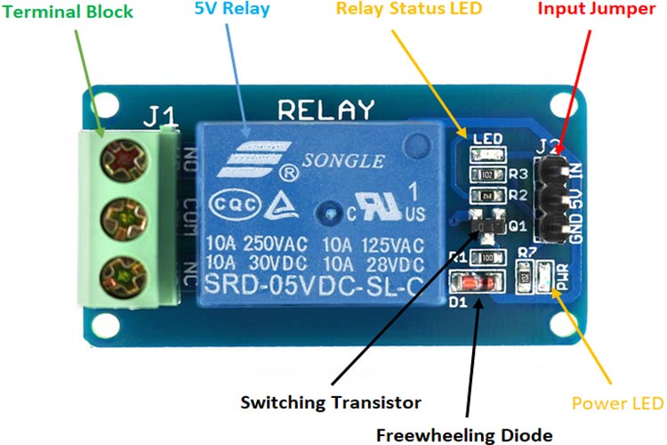
The pin configuration of the 5V relay module is shown below. This module includes 6-pins where each pin and its functionality are discussed below. Relay Module Pin Diagram Normally Open (NO): This pin is normally open unless we provide a signal to the relay modules signal pin.
Wiring A Relay Diagram
March 24, 2023 by Vikas Gariyal This article will show you the wiring diagrams of different relays. You will learn how to connect 4-pin (SPST), 5-pin (SPDT), and 8-pin (DPDT) relays to a circuit.
Relay pin configuration
1. Thinner cables can be used to connect the control switch to the relay thereby saving weight, space and cost. 2. Relays allow power to be routed to a device over the shortest distance, thereby reducing voltage loss. 3. Heavy gauge cable only needs to be used to connect a power source (via the relay) to the device. Why Use a Relay in a Car?
5 pin micro relay pin out diagram lasopasys
The lamp is connected to the relay using a normally open configuration. The Arduino controls the relay through pin 8 (pin 8 is connected to the relay IN1 pin). Finally, the PIR motion sensor is connected to pin 2. Demonstration. After uploading the code and wiring the circuit, you can test your setup.

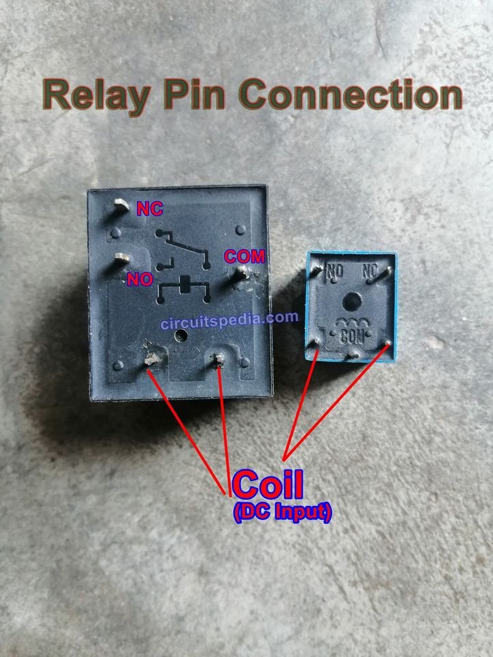
How to identify the relay pin terminal ? Find the Relay Pin configuration with Multimeter
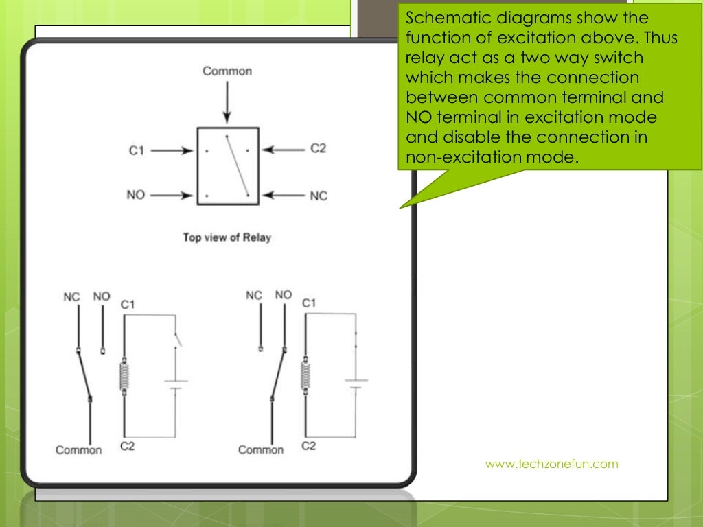
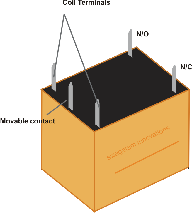
The relay is a remote-controlled switch that works on the principle that a tiny amount of current can be used to energize a little internal electromagnet. That electromagnet (a little coil of wire wrapped around an iron core) then pulls two internal switch contacts together that allow a much larger amount of current to flow.
How to Understand and Use a Relay in Electronic Circuits Circuit Diagram Centre
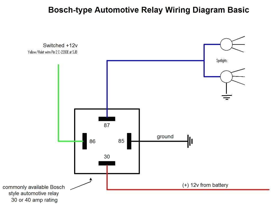
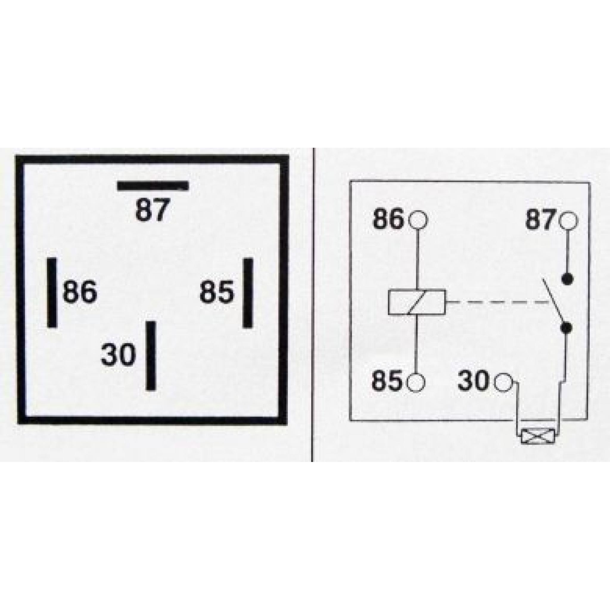
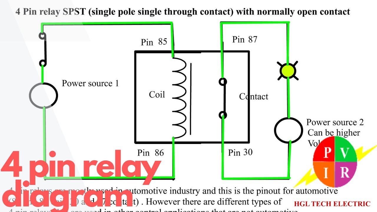
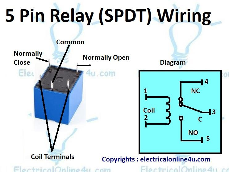
The relay has five pins which are labeled as follows: Pin 30 - Common (C) Pin 87 - Normally Open (NO) Pin 87a - Normally Closed (NC) Pin 85 - Coil+
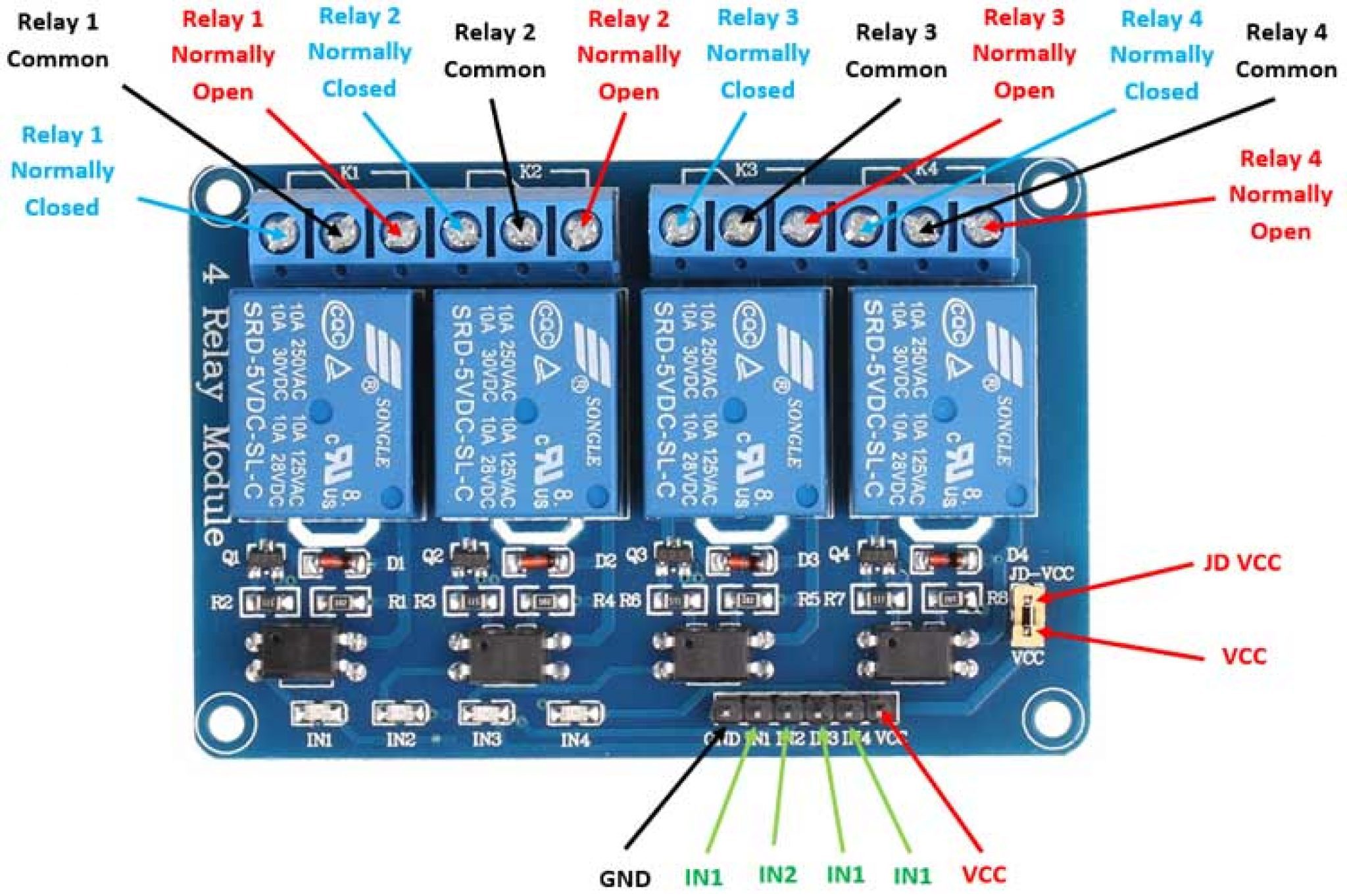
5v 4 Channel Relay Module FourChannel Relay Module Majju PK
1 As others have stated it is a dual/double pole relay. That is there are two independent three-way, or dual-throw, switches inside the relay. It is properly named a Double-Pole-Dual-Throw DPDT relay. If it helps, the diagram below may be easier to understand. simulate this circuit - Schematic created using CircuitLab

Relay Wiring Diagram and Function Explained ETechnoG
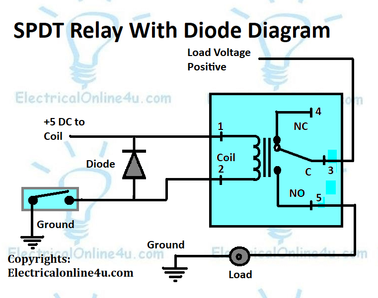
Relay coils give off high reverse-voltage spikes that will destroy sensitive electronic components. These spikes are generated by the coil - when the relay de-energizes - and the coil's magnetic field collapses. They are generally removed by fitting an external suppressor diode - across the relay coil. See diode D1 on this Repeat Timer Schematic.
Relay Wiring Diagram A Complete Tutorial EdrawMax
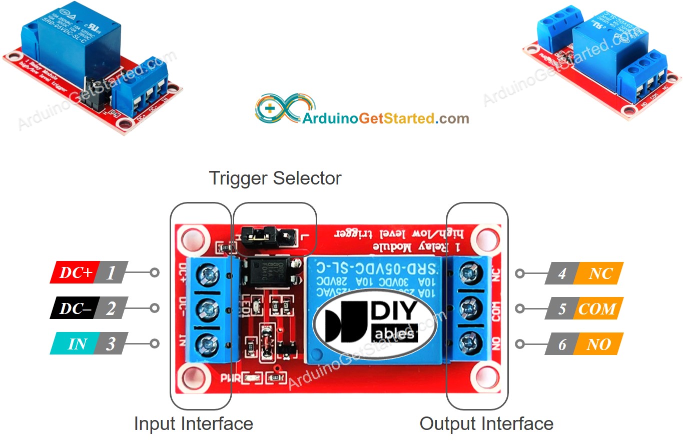
NO: Normally open 120-240V terminal. C: Common terminal. Ground: Connects to the ground pin on the Arduino. 5V Vcc: Connects the Arduino's 5V pin. Signal: Carries the trigger signal from the Arduino that activates the relay. Inside the relay is a 120-240V switch that's connected to an electromagnet. When the relay receives a HIGH signal at.

Relay 5 Pin Configuration 6 Way Trailer Plug Wiring Diagram
A 4-pin relay is an electromechanical device that allows a low-power circuit to control a high-power circuit. It is commonly used in automotive applications to control various electrical components such as lights, motors, and solenoids. The 4-pin relay consists of several components, including a coil, a set of contacts, and a housing.
Relay Types Relay Working How Relay Works Relay Operation
Relays and wiring can be a real pain, and the whole process of testing and diagnosing can be daunting. If you simplify it and break it into pieces, it's not.
5 pin relay wiring diagram starter Wiring Diagram and Schematics
5V 8-Channel Relay Module. The eight-channel relay module contains eight 5V relays and the associated switching and isolating components, which makes interfacing with a microcontroller or sensor easy with minimum components and connections. Each relay on the board has the same circuit, and the input ground is common to all eight channels.
How To Wire 8 Pin Relay
The input jumper contains the main VCC, GND, and input pins for easy connection using female jumper wires. Internal Circuit Diagram For Four-Channel Relay Module The circuit on the board is as follows: Each relay on the board has the same circuit, and the input ground is common to all four channels.
5V SingleChannel Relay Module, Pinout Diagram Components Monofindia
Single-Channel Relay Module Pin Description Single-Channel Relay Module Specifications Supply voltage - 3.75V to 6V Quiescent current: 2mA Current when the relay is active: ~70mA Relay maximum contact voltage - 250VAC or 30VDC Relay maximum current - 10A Alternate Relay Modules
5 Pin Relay Wiring Diagram Use Of Relay Electrical Online 4u All About Electrical
Incorrect Pin Configuration: Double-Checking Connections. Misidentifying or misconnecting the pins can result in a malfunctioning relay. This subsection will stress the importance of double-checking the pin configuration and provide tipson how to correctly identify and connect the pins to avoid any potential issues.
Arduino Relay Arduino Tutorial
Relay Pin Configuration Features of 5-Pin 5V Relay Trigger Voltage (Voltage across coil) : 5V DC Trigger Current (Nominal current) : 70mA Maximum AC load current: 10A @ 250/125V AC Maximum DC load current: 10A @ 30/28V DC Compact 5-pin configuration with plastic moulding Operating time: 10msec Release time: 5msec